
It is surprising where your mind wanders when you do something you do not really like, such as renovating a kitchen. I have just been there, read the book, seen the film, and played the video game. In the very beginning I had to rip out a wall and remove the old sink and 3-phase power to the old cooker. I then had to fit loads of 16mm copper pipe and loads of 2.5mm CSA power cable. So there I was, wishing I could do something else, such as play with radio, electronic, or anything even remotely technical.
I had loads of fantasy, plenty of time for thought, and with a bit of wire and a copper pipe in my hand I had a blinding flash of inspiration: "Can plumbing be used for radio?". Yes! it can. This article is only the first where I present my findings of the first experiment. It is hoped that you will come up with more clever ideas.
This description is nothing more than a VHF or UHF resonator, or a very stable LC tuned circuit with a reasonably high "Q" factor. This experiment will cover 100MHz to 200MHz. The advantage of this method is that the tuned circuit is also screened (to a large degree), thus reducing coupling by radiation.
Like all project we need some materials. Renovating a kitchen converts quite a lot of copper and cable into off-cuts and assorted installation debris. For this experiment you will need:
You also need a soldering iron capable of soldering copper pipe. I have one of these butane gas modellers torches that I use to pre-heat the copper, then I can solder using my fake Weller (Biltema) soldering iron. If you do not have such an animal, then you can put the work on an electric cooker ring and pre-heat to 180° Celcius (356° Farenheit). Then you can use a simple 15-Watt Antex iron. You will also need a 1.2mm and 5mm Dia. drill bits.
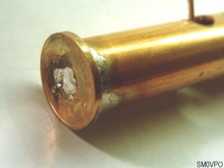
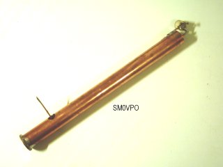
Heat up the copper tube and solder to one end the copper disk so that it neatly blocks the end of the tube. I found that this is best done by pre-tinning the disk and the end of the tube, then standing the tube on its end, placing the disk over the end, then heating until they sweat together. To the other end of the tube you solder a 2cm copper wire. This will become a fixing for the tuning capacitor, since you will not be able to solder directly to the tube.
At about 3cm from the bottom of the tube you drill a hole 5mm Diameter through the side of the tube. Drill a 1.2mm Diameter hole through the plate blocking the end of the tube Now solder a 1cm length of copper wire to one side of the hole. This is so that you can later solder wires to this to make an electrical conection. Now we are ready to fit the resonator.
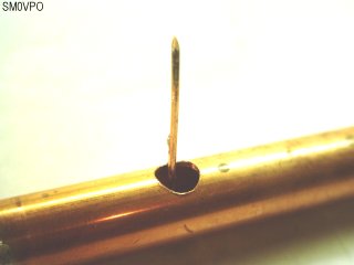
Pass the 22cm length of copper wire down the center of the tube and thread it through the 1.2mm hole in the end plate. Solder this in position. The wire should be quite straight before you enter it. It must NOT be allowed to touch the sides of the tube. From this point onwards you can allow the whole assembly to cool down.
Fit the 22pf trimmer cap top the open end of the tube. The two ground pins to the wire at the end of the tube, and the "hot" end of the capacitor to the center resonator conductor. The capacitor provides the mechanical ridgidity to support the resonator. For long (low frequency) resonators you could push a bit of dry plastic kitchen scouring pad down the tube, if extra support is needed. In principle the resonator will now reonate, and can be tuned over a 2:1 frequency range: from 100MHz to 200MHz.
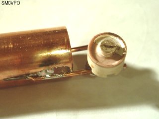
To make an electrical connection to the resonator you will need to attach a connection point. I used the 2cm bit of wire soldered directly to the resonator, through the hole in the tube. That's it, the resonator is finished. Now you just need find a suitable use for it. The tapping will be about 40-Ohms (at 200MHz), if you followed my directions.
Now we will deviate from my experiment and I will just document a few of my thoughts. In principle, this is just a method of construction for a stable, high-Q resonator, that can be used from about 50MHz to 500MHz, or more. The resonator I have given is 1/4-wavelength, and has an end impedance of about 200 Ohms (at 200MHz). The length of the resonator should be about 4000 / F(MHz) = cm. This will give a little leeway and the resonator will work a couple of % over this figure. But you will need to experiment a little.
The resonator can be used as a normal tuned circuit to build filters and oscillators. Two tappings on the coil can be used for the typical inverted Hartley oscillator.
Tapping coils is never easy to decide, but they should be found by trial and experiment. A good starting point would be 10% and 20% of the length of the resonator. This circuit will not affect the frequency of the tuned circuit since no connection is made to the top of the tuned circuit.
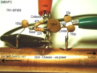
Here I have drilled the second hole up the resonator (the one to the left above), added the second tapping to the coil and got the Hartley working. If you listen to the oscillator on the 145MHz band it sounds quite unstable, but pushing a bit or kitchen scouring pad around the resonator made it wonderfully stable. I did take the liberty to change a few values, mainly because I used the first components I put my hands on (I'm a lazy old "Git"). The tuning capacitor is 10pf - 60pf.

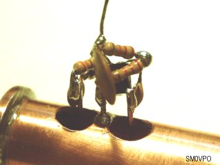
Here I have pushed the resonator to the frequency limits of the BF959. The length of the tube is 6cm, and the tappings on the resonator element are 9mm and 18mm respectively. This corresponds to 15% and 30% of the resonat element length. The two base bias resistors are each 22K, and the emitter resistor is 330 Ohms. Note that the emitter resistor is returned to ground through the resonator. This was "on the edge" of oscillation using the BF959. This device has an ft=1.1GHz and this is half way there. For more reliable oscillations I suggest you use a device with ft=1.5GHz or more, but you could try with different tappings. The tuning capacitor is 2.5pf to 10pf
If you do not want to play about with boring holes in the side of the tube, then the top of the resonator can be connected directly to a transistor circuit to form the classic Colpits oscillator.
The Colpits oscillator is easier to construct since you do not need to drill the copper tube for tappings. But in this application the upper frequency limit will be lower than 200MHz because the 10pf feedback capacitors are also affecting the tuned circuit capacitance. In practice you can reduce the value of the 1n0 capacitor feeding the base of the transistor. 10pf or less would be a good figure here, as long as it will still oscillate. The two 10pf capacitors govern the feedback ratio. The upper cap can be lowered to increase the feedback.
As a filter, you can use a single resonator to "shunt" out-of-band signals, but you can also use a very light coupling between two resonators; using one resonator as the input, and the second as the output circuit.

There is no reason why you cannot double the length of the resonator with a short-circuit at both ends and the capacitor in the centre. This will put it in the 1/2-wave mode. You can couple signals into one end and out of the other end.
The terminal impedance is quite low, but if you should try to use this for high-power RF filtering, such as in transmitting equipment, then be aware that there will be high RF voltages at the "hot" end of the resonator. The tube may not be wide enough to tolerate these voltages.
Have fun, and remember that most "boring" tasks can have their uses :-)
Best regards from Harry - SM0VPO
Dont forget to visit my messageboard if you have any questions about this or any other project. I always look forward to receiving feedback, positive or negative. You do not have to register to post messages.
Very best regards from Harry Lythall
SM0VPO (QRA = JO89WO), Märsta, Sweden.
EA/SM0VPO (QRA = IM86BS), Nerja, Spain.