

I recently purchased quite a lot of the old "battery valves" at a junk sale. It seems that there are quite a few of these valves around as it is common knowledge that valves are obsolete so no-one wants them. If you are not too particular what type of valve you want then there are lots of valves available.
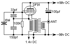
Above is the circuit of a simple single valve transmitter and it uses just one of these battery valves. You can use almost any type of battery valve, but my first experiments used a DF91. It would be a little better to use a DL91 or some other valve rated at more suitable anode current, but the DF91 works well. You can also use:
DL91, DL92, DL94, DL96, DF91, DF92, DF94, DF96, 1S4, 1T4, 1L4, 3V4.
The circuit is a very simple oscillator that will give an output of up to one watt. The only critical component is the isolating/output coil in the cathode (fillament). This is wound upon a 1/2" dia ferrite ring and consists of 17+17 turns of wire to connect the 1.4 volt fillament supply to the valve fillament. The two enamelled wires must be twisted together before winding.
The output from the transmitter is taken from the same coil, by adding another winding of just a few turns. The number of turns will depend upon the valve used, but a good starting point is five turns.
The oscillator will only oscillate at the FUNDAMENTAL frequency of the crystal which limits this transmitter to the HF bands. The crystal may be replaced by a parallel tuned circuit for VFO operation. This tuned circuit should be of a fairly high "Q" and mechanically ridgid to make the oscillator stable and to prevent drift, especially when keyed.
Keying is achieved by keying the +90v HT but it is adviseable to use a little capacitance across the supply and a resistor in series with the key to improve the keying waveform.
You should be able to build this project in an evening if you have all the components available.
Have fun, de HARRY, Lunda, Sweden.