
This turned out to be quite an interesting project. It all began as a project for a paying customer, but I found that the circuit had quite a lot of advantages over previous similar projects. It is basically an inverter for converting power from 12v DC to something else ...
You can use the circuit as shown to convert 12v DC to 230v AC (117v AC), or even use it to convert 12v DC to 24v DC. The output power of the AC version is about 30 Watts, which is enough to power three medium sized (11W) ecconomy lamps, or about 8 of those small 4W lamps that each give the same light as a 20-Watt lamp. You could even rectify the output to get 250vDC to power valve equipment.
The DC-AC version can be adapted to generate 6vAC, in addition to 230v DC for portable operation of old valve (tube) based equipment. An EL84, for example, will deliver over 10 Watts of RF in the HF band, and the efficiency is still comparable with transistor devices. The heated cathode takes just 2 Watts.
The 12vDC 24vDC or -12vDC configuration will deliver about 3 Amperes at 24v 65 Watts, or -12v 32 Watts. To do this you convert 12vDC to 12vAC, full-wave rectify this and put the new isolated 12vDC in series with the input 12vDC. Your output will then be 24vDC at 3 Amperes, for 6 Amperes input. Reverse the diodes and reference the rectifier to ground and you will get -12v at about 3 Amperes for 3 Amperes input. See below:
But as a DC-AC converter, the output frequency accuracy is good enought to run a clock-radio for a short duration of time, without gaining or loosing more than a few seconds per day. The important bit is that you choose stable capacitors and take care to get the frequency right. You should be able to get it better than 0.1% with just a little effort.
The circuit consists of an oscillator and a push-pull current amplifier. See figure 1 below.

The heart of the waveform generator is the CD4060, which is used as a free-running astable oscillator and divider. The output is taken from Q8, which means the oscillator is succesively divided by 2, eight times. Total divide rate is 256. If you want to generate 60Hz then the the oscillator is adjusted to 60Hz x 256 = 15,360Hz. If you want 50Hz then set the oscillator to 50Hz x 256 = 12,800Hz. The capacitor C2 is a 2.2nf (2200pf) mylar type. You can also use a 2200pf polystyrene type. The important thing is that you use a stable cap here. Ceramic capacitors cannot be used.
The resistor marked Rx on the circuit is composed of three resistors in series. These you must select to get the correct frequency. A frequency counter is essential here. If you do not have a counter, then you can compare the frequency with your mains frequency using a dual-trace oscilloscope. You should be able to get the two traces to remain stationary. If you couple a counter to the oscillator you will alter the frequency, so instead couple the counter to the CD4060 pin 7 (Q4) and select the resistors for 800Hz (50Hz), or 960Hz (60Hz).
The CD4060 is powered from 5vDC which is derived from a 78L05 regulator chip. I have managed to blow up these devices! The output is protected, but if you have too high supply voltage then they do get a bit hot. I therefore tend to use a resistor in series with the input supply so the cheap resistor burns a few mW of power, thus saving my 78L05 from an excessive input voltage. See R1 in the circuit diagram.
In my first prototype the resistors for 60Hz were 10K + 1K0 + 180 Ohms (11,180 Ohms). In my second prototype I needed 10K + 3K9 + 680 Ohms = 14,580 Ohms. The thing to do is to put in there a 10K resistor and measure the frequency and resistor value. If you get 1036Hz and the resistor is 9.97K, then use the formulas:
1036 x 9970 / 800 = Ohms (50Hz)
1036 x 9970 / 960 = Ohms (60Hz)
Note that a 10K resistor is seldom 10K. A 5% resistor can be up to 500 Ohms higher or lower.
The output of the CD4060 (Q8) is buffered by an NPN general-purpose transistor, TR1, and inverted by the second transistor TR2. This gives us two seperate square-waves that are in anti-phase.
TR3a, TR4a and TR5a are cascaded common-emitter power inverters driven from phase-a. TR3b, TR4b and TR5b are cascaded common-emitter power inverters driven from phase-b. TR4a and TR5b are cross-connected to give a power-up/power-down drive. TR4b and TR5a are cross-connected to give an oposite power-up/power-down drive. This gives the push-pull drive to the output transformer.
One advantage of this push-pull design is that there is always a low-impedance drive to the driven transformer winding. This supresses spikes and transformer ringing, but add a 0.1uf 50vDC capacitor across the transformer if you want to be really safe. In DC/DC applications a 250vDC output could otherwise drift up to 270v without a load.
The circuit shown is powered from 12vDC input (13.8vDC). In practice you can run it from 10v to 18v without a problem. The 180R resistors are all made up using two 330R 1/2-Watt resistors in parallel to form a 170-Ohm resistor, 1-Watt. This way is cheaper than buying higher power resistors.
If you want to power the inverter from 24vDC input then change every 330-Ohm resistor for a 1K-Ohm 1/2-Watt. This includes the resistor R1, in series with the 5v regulator.
As with all my inverters I use either home-wound transformers, or commercial mains transformers fed backwards. If you have a nice 36-Watt 12v-0-12v mains transformer then you only need connect the 12v-0 to the inverter circuit. If you have a 6v-0v-6v transformer then use the two 6v terminals and forget about the 0v centre-tap. 6v-0v-6v = 12v-6v-0v when looked at from a different perspective.
If you want to run the inverter from 24vDC input and still get 230vAC (117vAC) out then you can still use that 12v-0v-12v secondary, but use the whole secondary winding: 12v-0v-12v = 24v-12v-0v. Easy :-)
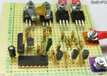
The first prototype was assembled on prototype board. The only heatsink required to deliver full output was the solder tags to the power transformer and optional smoothing capacitor. I have included this for interest sake, because do do not always need a PCB.
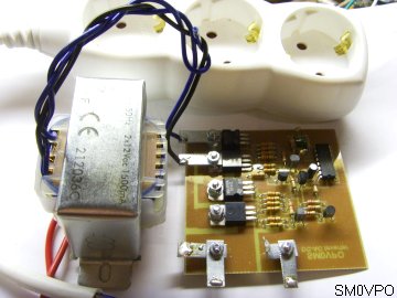
The second prototype uses a PCB, but I forgot the add the protection diodes. But it works well without them, so I have included this for your perusal.

Here is a view of the complete unit, just as I tested it and put it to use. Now I do not need it because I shall build the latest version using the 1N4001 protection diodes, so I shall give this prototype it away to a friend who can make use of it.
The printed circuit board foil pattern is available for download fom my download section. The filename is "inverter_push-pull.zip".
I hope that you leave learned something and have fun with this information. Very best regards from Harry - SM0VPO
Return to INDEX page