
I have previously written an article on DIY transformers, so that you can rewind them yourself using an existing source of "donor" transformers. The article is great and I have used those techniques for many years. However, the article requires a lot of effort and winding every coil, together with the calculations and such. The prices of the donor transformers has also risen 3x since writing it. But I now find myself in a slightly different situation:
What I really want to achieve is a little two valve, amplifier and timebase generator for my oscilloscope (still under construction in Sweden). For this I need 6.3V AC @ 600mA (4 Watts), and 220V AC @ 25mA (6 Watts). In reality I shall only run the anodes at about 2mA to 5mA, so my HT power requirement is only about 2 Watts. If you are wondering why I need to use valves (tubes), it is because I need a signal voltage of at least 150v for the deflection plates of my Cathode Ray Tube, so I need an HT voltage of about 300V DC. 220V AC rectified will give me 311V DC.
300V DC is not so easy to use with transistors. I have also learned that I need less than 3mA at 220V AC to get 1200V DC for the tube. That's less than a watt, and it is the astig, focus and brightness controls that draw most of the current. I can do both jobs with one simple transformer, although I will need an additional small 5-Watt transformer for the CRT heater, suitable for withstanding -1200V DC. But more about that in the next project.
I found these really cheap transformer-type "battery eliminator" power supply units in a Chinese shop in Nerja, Andalucia, Spain. The price is US$5 each, and they offer 7 different voltage settings at up to 1000mA. Unfortunately this is pure bovine excrement. You can also find sources of the old power units for old computer modems, cordless drill chargers and such things. Modern power units use Switch-Mode technology, but they are no good (and are easily blown by lightening). If you see these things at junk sales, just feel the weight: Heavy = transformer, light = Switch-mode.
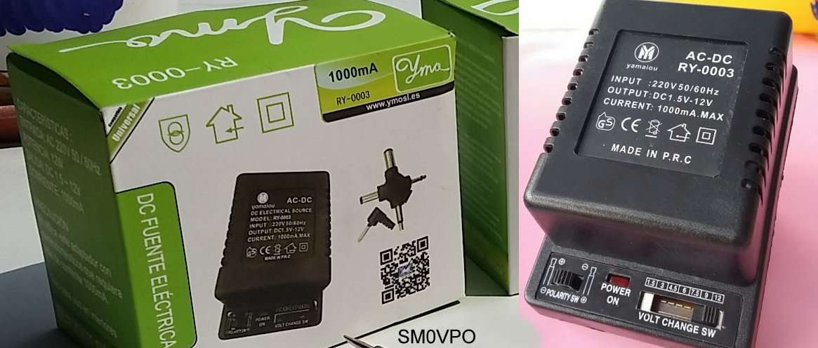
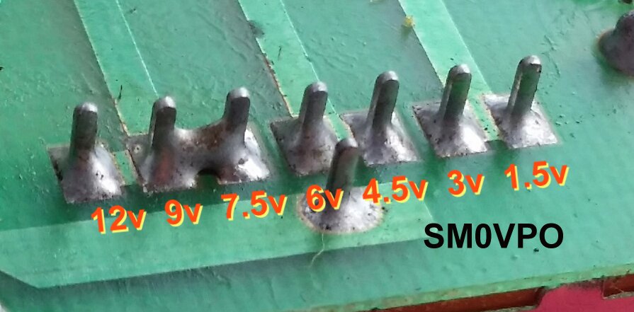
The 7-step voltage switch has several switch contacts deliberately connected together so that you always get 16.1V DC if you select 7.5V, 9V or 12V. If you don't believe me then here is the etched PCB with the switches shorted:
But anyway, these transformers are great for cannibalising. Instead of stack-wound windings (several coils on one former), each winding in these units is wound on a seperate module. Two modules are stacked and 30 of the "E"s and 28 "I"s are filled with the ready-wound modules. This gives a coil former with a center-hole of 16mm x 16mm. The slot in the "E"s will accept 24mm of coil, so each module has 12mm outside width. The slot in the "E"s will accept 8mm of wire, including the former thickness, so realistically you have 7mm absolute maximum to play with.

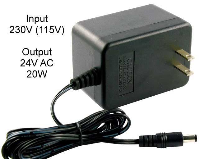
An alternative transformer can be those 20 Watt 24V transformers that you get for outdoor Christmas tree lights. They all seem to have exactly the same dimension laminations, so that you can stack them to get larger power ratings, and even mix laminations: there seems to be some form of standard. The Christmas tree lights transformers have 60 laminations stacked, and also use pre-formed winding modules.
If you have several transformers from different manufacturers then you should do this check for each of them. It is important that the two transformers we are using for this project both have the same number of turns per volt. There is normally sufficient space over the existing coils to thread some 0.3mm Dia. enamelled wire to make a test coil. Thread 15 turns or so, taking care not to scratch insulation off the enamelled wire while threading.
Connect 230V AC to the primary winding and check the voltage from your 15-turn coil. If you have used the same 12-Watt model I chose, then you should measure 1.000 V AC using a digital voltmeter, if the input voltage is 230V AC. This is because the primary winding is wound selecting a turns to voltage factor of 15 turns per volt. If you get any different reading then divide the measured voltage by 15 (or the number of turns you put on as a test coil).

I only had a bit of 1mm Diameter wire available, so I only was able to put 12 turns through the gap. If for example you get 1.363V AC and the test coil was 15 turns, then 15 / 1.363 = 11.00513573000734 turns per volt. I got a voltage of 0.867V AC from mt 12-turn coil, but the mains voltage was a little less than 214V AC that day. This is Spain! So corrected for 230V AC, my turns per volt will be:
This means that to get 6.3V AC for my valve (tube) heaters I need 6.3 X 15 = 94.5 turns of wire. This wire I managed to salvage from one of the Christmas-tree lights transformer. I found that the 24v 20W winding used 0.5mm Dia. enamelled wire. According to my table, 0.5mm Diameter will give me 500mA. A bit close to the limit, but plenty good enough.
When I measured the pre-wound 230V coil module of my transformer, I see the inside cheeks are 9.5mm apart, and there is 3.5mm of clearance on top of the winding for a new winding of my own. This gives me an area of 33mm� to wind the new coil. 0.5mm Dia. wire will give me 4 turns per square mm, or 18 turns per layer, so I will need 6 layers, or 3mm of height. This is cutting it a bit fine, but if I am very careful with the first couple of layers then I can probably make it. Here is a wire table to help you choose the correct wire gauge:
| Diameter (mm) | AWG | I-maximum (mA) | Length per 100g reel |
|---|---|---|---|
| 0.05 | 44 | 3.8 | 8200 |
| 0.10 | 38 | 24 | 1400 |
| 0.15 | 35 | 54 | 620 |
| 0.20 | 33 | 75 | 438 |
| 0.25 | 30 | 147 | 227 |
| 0.30 | 29 | 212 | 157 |
| 0.35 | 27 | 288 | 118 |
| 0.40 | 26 | 377 | 88 |
| 0.45 | 25 | 476 | 69 |
| 0.50 | 24 | 585 | 56 |
| 0.60 | 22 | 849 | 39 |
| 0.70 | 21 | 1150 | 29 |
| 0.80 | 20 | 1490 | 21 |
| 0.90 | 19 | 1850 | 18.5 |
| 1.00 | 18 | 2350 | 13.5 |
| 1.50 | 15 | 5250 | 6.3 |
| 2.00 | 12 | 9350 | 3.4 |
So the wire will work. I have the transformers, I have the materials I need. Now let us play.
Begin by stripping down the two power supply units, throw away the cases and unsolder the power connections. Keep the PCB. There is a good switch, a bridge rectifier and a 1000uf capacitor on there. You may like to use a bit of masking tape to seperate the secondary connections and mark the voltages, just in case you want to wind another transformer using the ready-made coil modules that are not used here.
Remove all the "E"s and "I"s from the two transformers. The first E can be bit of a bugger to remove, but using a stanley knife, you can usually break the seal between the first lamination and the rest of the pack. Using an electricians flat-bladed screwdriver you can push the first lamination through the coil assembly by gently tapping it with something weighty, but not too heavy. Once the first lamination has been removed then all the other can be simply lifted out. Take care not to bend them. When both transformers have been dismantled, you need to save only the two 230V windings. The pre-wound low-voltage modules can be saved as formers for another project.
Inspect the windings carefully. Some of these cheap transformers are a little untidy when they wind the coils. There can be the odd primary turn that protrudes 1/2-way up the side of the former. If you wind a new coil on top of this then there is a risk for a short-circuit between coils. You can ease the turn back in place before winding, using a insulated tool and no force. It can help to add a layer of tape to insulate the renegade turn.
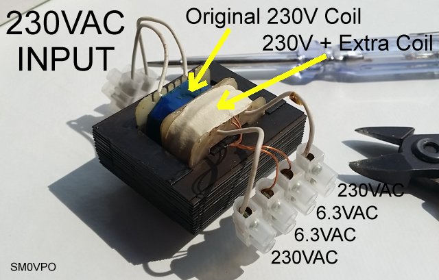
Take one of the pre-wound 230V modules and add a new winding of your own on top of it. You need 94 turns, in our example. Keep the winding as neat as you can and wind in neat layers, otherwise you will occupy too much space. It is better to have a couple of turns too little than have the coil coming into contact with the laminations after assembly. Put a layer of masking tape on your winding when it is finished.
Now assemble the transformer. Stack the two 230V windings (one with your additional coil) by putting "E"s in, alternately from either side, until the former is full. It should take about 29 of the "E"s, and the last one will be be a bit of a squeeze. Now fit the "I"s in the end-slots between the "E"s. That's it! Transformer is complete. All you need to is fit block-connectors and then test the transformer.
Testing is very easy, but you must do a few basic checks to be sure that it is functioning OK and not in any way dangerous. When doing these tests keep your fingers off any contacts. 230V AC at 30mA is still several times more than is enough to kill you. Take care so that you don't come complainimg to me that I didn't warn you.
1 - Measure the electrical resistance, between any combination of windings, which should be too high to be readable, that is greater than 10 Meg-Ohms. If this test fails then you have a short between coils, or some other form of leakage, such as moisture.
2 - Connect a 230V (115V) 15W tungsten lamp in series with the 230V primary winding. Switch ON the mains power and check that the lamp does NOT light up. If this test fails then there could be a shorted turn, or the laminations are shorting to each.other. In this case you need to remove the laminations, wash them in acetone, spray-varnish one side, and re-assemble the transformer.
3 - Measure the two secondary voltages. You should have 6.3V and 230V at the two secondary windings. There should be no volts between any winding: 230V primary to 230V primary, 230V primary to 6.3V secondary, and 230V secondary to 6.3V secondary.
4 - Measure the voltage between Earth (ground) and 230V secondary, Earth (ground) and 6.3V secondary, and Earth (ground) and the laminations.
If you want to load the transformer then remove the 15W lamp and connect the transformer directly to you 230V mains supply. Use a 6V 500mA (3W) lamp on the 6.3V output. You can also connect a 230V 5W LED lamp across the 230V output. The regulation of these transformers is not too good, but you should still see at least 6V from the 6.3V winding, and more than 200V from the 230V winding.
The transformer should stay qute cool if you run it for 30 minutes, or so. If it gets "hot-to-touch" then the laminations may need to be varnished. These transformers usually use a cost-effective chemical treatment between the laminations to insulate them. Occasionally the chemicals just reduce the resistance and not insulate them. Note that if you do need to varnish the laminations, use as thin coat of varnish as possible. The more varnish you use so the fewer laminations you will be able to fit into the assembled transformer.
Now that you have a transformer finished, you will still have sufficient laminations and two coil modules left over to make another transformer. You can rewind one of the modules for 115V (1725-turns) or 230V (3450-turns). Without rewinding you can make a 6V to 12V converter, using a pair of transistors, or a 12V AC to 6V AC transformer - more efficient than a voltage regulator.
Well I hope that you have learned something useful with this information. Very best regards from Harry - SM0VPO
Return to INDEX page