
Introduction
I am presently engaged in a project that requires an addditional voltmeter to be permanently connected in circuit, to monitor the loop voltage of a synthesiser.
I only have two multimeters and they are already in use. So I thought about using a simple Operational Amplifier and a cheap'n nasty moving coil meter movement, to make a high-impedance DC voltmeter. But have you seen the prices of them? A new multimeter costs less than the meter movement.
But I do not need any accuracy; I just need to read 0-8v with +/-0.5v accuracy. Ok, so I have had to stop the synthesiser project for the moment to knock-up this little gem.
The Circuit
I had thought about using an LM3914 "bar-graph" generator circuit, but again they cost a packet (US$6 each), at least here in Sweden they do. But two Quad-OpAmp chips (LM324), cost almost nothing (US$1 for the pair). A bargraph generator is nothing more than a slack-handful of OpAmps, all thrown into a single chip. It is cheaper to use the LM324 and put in the few extra components needed. Here is my circuit diagram:
As you can see, there is nothing clever about it. I have not bothered to show the IC pin numbers, but you should have no problems if you use my PCB. The resistors R1 to R8 down the left all form a voltage divider from the 7.5v Zener diode. The resistors give me taps of 0.5v, 1.5v, 2.5v, 3.5v, 4,5v, 5.5v, and 6.5v. The top of the zener gives me the eighth voltage: 7.5v. These reference voltages are all connected to the negative-acting input of each OpAmp, and all the positive-acting inputs are gathered together for a common input. With 0v on the +ve inout, the output voltage of avery OpAmp is 0v.
If the input voltage lies between 0v and 0.5v then no LED lamps will light. If the input voltage rises to between 0.5v and 1.5v (1v +/-0.5v) then the first LED will light when the first OpAmp +ve input exceeds the -ve input threshold. In this way the LEDs all form a nice bar-graph display in 1v steps, +/- half a volt.
The A-B-C links should be in the A-B position for a normal bar-graph display, when each LED succesively lights as the voltage rises. With +4v input there will be four LEDs lit. If you fit the links in the A-C position then only one LED will light for each voltage step, to give a moving dot display. The top (last) link should always be in the A-B position for both modes. This what I did when I photographed the prototype.
Another small point, the PCB I provide has LED mounting holes that are 2.54mm apart, and BOTH both sides of the LED. If you look carefully enought you can just see this in the prototype picture below.
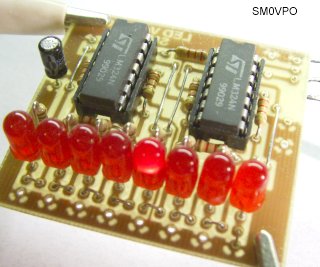
There are a couple of corrections to the PCB. This is the first prototype board that I had to "carve" in a couple of places. The corrected PCB is to be found on my download section (shortly). I shall add the PCB foil for 8, 12, 16, 24, and 32 LEDs. In the prototype I photographed I did not use the zener diode. You can just see that I have a potentiometer hooked into circuit to give me a variable 0-10v inhput signal.
Extending It
If you want to extend the board to have more than 8 LEDs then you can do this usinmg two (or more) boards. For a level meter then the 8-LED display should be enough, so you are probably be wanting the moving dot display.
For a moving dot display using two or more boards, the upper A-B-C link is removed and the point is connected to the "X" contact in the second board. The uppermost A-B-C link in the second board is set to A-B. In addition to this, the 1K0 resistor in the second board is removed and the point is connectd through a 2K2 (R1) resistor to the V-ref input of the first board. The Zener and associated resistor is not fitted in the first board. The V-in terminals of both boards are connected together.
The above modifications will give you 16 LEDs that switch on in 0.5v steps, +/-0.25v.
Another modification is to drive the board from a simple diode detector and capacitor, so the board(s) will display RF or AF voltage levels. Change the 7.5v Zener diode to a value equal to the maximum peak input voltage. You could even remove the zener diode altogether and use an external reference voltage.
The resistors R1 to R8 need not neccesarily be equal. As shown, they are all equal to give a linear voltage display for my application. But for use as a level meter they should have other values. For example use R1=100R, R2=220R, 470R, 1K0, 2K2, 4K7, 10K, and R8=22K. This will give a progressive, non-linear display. This is what they did when they created the LM3915 logarythmic bar-graph display. The LM3914 is linear. As a VU-meter, change the first four LEDs to green, the next two to yellow, and the top two to red.
When used to monitor the DC loop-voltage of my synthesiser, I can see the synthesiser frequency as the loop voltage rises and falls. If I change the frequency program then the LED indications change. This can be used to make a simple frequency meter, but that is probably best left to be another project. Right now I have built my extra voltmeter so I can return to the synthesiser project.
Very best regards from Harry - SM0VPO