
I have answered loads of questions related to the unsuitability of Veroboard and Breadboard for radio frequency circuits. So what method of construction is suitable for radio frequencies?
PCBs are great for volume production or where you want a nice neat job. For "quick'n cheap" or prototyping, there is nothing to beat taking a large bit of copper-clad board and just soldering the components together on it. This method of construction is great for RF, even up to the UHF band.
The method I use is to take a bit of copper-clad board and super-glue a strip of copper-clad board to it. This strip is my +ve supply rail. So at one end of it I solder a large electrolytic capacitor to ground, and at the other end a smaller capacitor, usually 1nf or 10nf; anything in that area. ICs are also super-glued to the copper groundplane with their legs in the air, just like a dead insect.
 |  |
|---|
All that you need to do now is to mount the other components on the board. It may occur that there is too much hanging in the air and needs a little support. In this event you can solder a 10Meg resistor to the groundplane and use the resistor as a support insulator. I prefer to superglue small squares of copper-clad board to the ground copper plane and use these. This technique is also great for making anchor pads for external connections, as shown in the second picture below.
 |  |
|---|
Don't forget that strips of copper can also be used as resonators or tuned circuits for VHF/UHF circuits. The supply strip can also be cut with a hacksaw to break only the copper land, thus forming another isolated pad. Here are a couple of my projects built using this technique. Click on the pictures to view the project files.
Basic RF (HF) Oscillator +
Calculators |
500mW QRP Linear Amp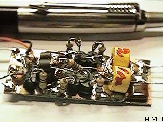 |
|---|
The final projects may not look very pretty, but they are small, stable, repeatable and require no board preparation, other than cutting to size (and that can be done after the project is assembled). Component to ground capacitance is also low, often better than a double-sided PCB with groundplane. The copper land area has so little resistance or inductance that circuits will work well up to about 1GHz and even beyond. In fact, I have built circuits that work "ugly" style, but become somewhat degraded when transfered to PCB.
If you need to screen a part of the circuit, then solder a bit of copper-clad board vertically to the groundplane as a partition. You could totally enclose the circuit in this way, or even make it water-tight. The correct construction method is any one that works. The best construction method is the one that works best.
Have fun, de HARRY, Lunda, Sweden.