
I have been asked if I would provide some basic information regarding valves (tubes) and how to use them. Here I shall give some basic information about construction and a few simple uses, each of which may be used as a building block for larger projects. This document is NOT intended to be a major comprehensive work, but to provide a little information to get you started. From here onwards you must follow your own path of self-education.
If you look into the bottom of a valve you will see the wires from each electrode and you can see the valve base pins to which they are connected. For this reason I will not give any valve data or pin-outs. These are widely available from other sources and most pin-outs can be worked out visually.
I do not know why it is called a DIODE. With only two electrodes I reckon it should be called a BIODE. Basically, when an electrode (CATHODE) is placed in a vacuum, coated with Barium Oxide and heated to several hundred degrees, the electrons on its surface become more agitated and form a cloud around the cathode's surface. From this cloud of electrons it is easy to attract electrons to a positively charged electrode (ANODE). The anode only needs to be placed in the same vacuum as the cathode. Electrons will flow from the heated cathode to the relatively cool anode, but electrons will NOT flow from the anode to the cathode because there is no Barium Oxide coating on the anode and it is too cold. We have formed a DIODE valve. Here are the circuit symbols.
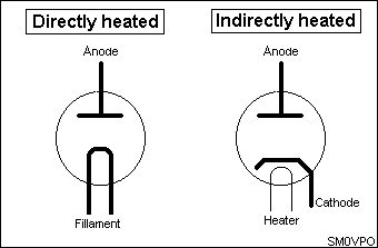
Note that there are two methods of heating the cathode:
DIRECTLY HEATED
The cathode is a bit of filament wire coated with Barium Oxide and a current is passed through it to make it get hot. One of the two filament terminals is used as the cathode connection. This method of heating a valve cathode was most often used in battery portable equipment and HT rectifier valves. The filament voltage is normally 1.4 volts for battery valves such as 1T4, 1L4, 1S4, DF91, DL91 etc. Directly heated HT rectifier valves commonly used 5 volts to heat them. Early valves used only 2.5 volts for the filament.
A huge disadvantage of a directly heated diode is that current flowing from cathode to anode is added to the filament current. If this current becomes too large then the filament can become too hot and burn out, just like an overloaded torch-bulb.
INDIRECTLY HEATED
The non-coated filament wire is inserted into a Barium Oxide coated metal tube and insulated from it. The filament is only used to heat the cathode tube and so it is normally called the HEATER.
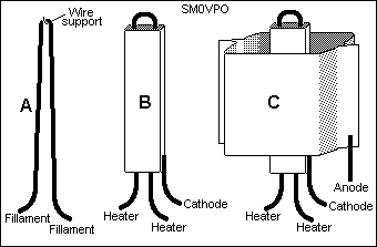
Here you can see a typical diode valve construction. (A) shows a typical filament wire with a wire support hook. Some valves use the wire support hook to make a direct electrical connection to the filament wire. This connection is used as a centre-tap for the cathode connection. Centre-tapped filaments are usually 2.8 volts; 1.4 volts between the centre-tap and each filament connection. (B) shows a typical indirectly heated cathode. (C) shows the anode assembled around the cathode. The anode may be circular or a variety of weird shapes.
The diode valve is in many ways far superior to semiconductor diode because a semiconductor diode requires a certain voltage across its terminals before it begins to conduct. The vacuum tube diode does not suffer from this effect, making it an ideal and sensitive RF/IF detector.
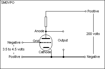
Ok, so now we have a diode. If you were to place the diode valve across a 200 volt power supply, several things will happen:
Semiconductors will blow in microseconds whereas valves may last several seconds before something happens. In this way valves are more forgiving than transistors.
To make an amplifying device (and to prevent the catastrophic scenario above) we need to regulate the current flowing from the cathode to the anode of a valve. If we insert a wire mesh or GRID between the anode and the cathode we can control the electron flow and so we have created a TRIODE:
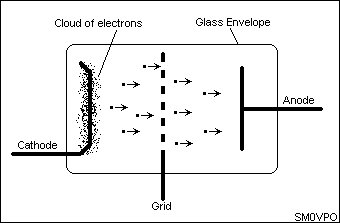
This grid is called the CONTROL GRID. With a few hundred volts positive on the ANODE and the negative on the cathode, electrons from the electron cloud around the heated cathode will go coursing their way towards the anode. But the wire mesh/grid is in the way, no problem; they just go through the holes. But if we connect a small negative voltage to the grid (with respect to the cathode) then the wires of the grid will have a field around them that will repel electrons. This field of repulsion will effectively reduce the size of the hole the electrons can pass through, thereby reducing electron flow and the anode current. If the negative voltage on the grid is made even more negative then the field of repulsion around each grid wire can become so wide that they all join up. This will cut the valve off totally and NO electrons can flow from cathode to anode.
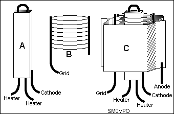
Here is the typical construction of a triode valve. The same cathode (A) is used as for a diode, but a grid (B) is placed around it. The grid is commonly composed of two vertical lengths of wire about 1-2mm Diameter spaced about 1 cm apart. Between these two wires a very thin 'hair-like' wire is wrapped around loosely so that it forms a circular or oval cylinder. The grid wires are spot-welded to the two vertical wires.
A typical triode valve will control an anode current by means of varying the voltage on the valve's grid. Typically, the anode will be 2mA (0.002 Amperes) for a grid voltage of 4 volts NEGATIVE (with respect to cathode). If we vary the grid voltage from -3.5 to -4.5 volts the anode current will vary, typically, from 1mA to 3mA.
If we place a 50Kohm resistor between the anode of the triode and the +200 volt supply, then the standing voltage on the across the resistor will be:
E = I x R = 0.002 x 50000 = 100 volts
By varying the grid by 1 volt (-3.5v to -4.5v) the anode current changed from 1mA to 3mA. The CHANGE is 2mA. The 2mA change will give us a 100 volt change across the anode load resistor. One volt signal in = 100 volts of signal out. Voltage amplification factor is therefore 100, and this figure is quite typical for a valve.
Note that there is no current flowing to or from the grid under normal conditions. The grid input impedance is therefore not far from infinity.
The triode characteristics we are normally interested in are:
| Function | Abbr. | Units | Typ. |
|---|---|---|---|
| Heater Voltage | Vh | Volts | 6.3 |
| Heater Current | Ih | mA | 250 |
| Anode Voltage | Va | Volts | 250 |
| Anode Current | Ia | mA | 3 |
| Control Grid Voltage | Vg | Volts | -4.5 |
| Mutual Conductance | Gm | mA/V | 2.5 |
One of the biggest problems with the triode valve is the small current it will handle. Anode currents of a couple of milli-amperes are of little use for powers above about half a watt. For radio frequency use, the capacitance between the anode and the control grid of a valve can become a problem by providing unwanted feedback. Earlier triode valves used anodes or grids mounted at the top of the glass bulb as an attempt to get the connections as far away from the others as possible.
Another solution was to insert a second grid between the control grid and the anode. This additional grid was called a SCREEN GRID and a valve with two grids is called a TETRODE.
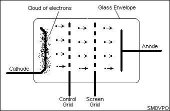
The valve may still be used exactly as a triode, but a few hundred positive volts are applied to the screen grid, usually about 66% of the anode voltage. Electrons whizzing past the negative control grid are retarded, but immediately after the control grid lies a few hundred positive volts on the screen grid, so the electrons continue their journey with renewed vigour. As they get to the screen grid they will feel the influence of the anode with its higher potential and so the majority will head for that.
When the electrons flying through a tetrode hit the anode they can knock electrons off the anode plate due to the impact. Most of these 'liberated' electrons become attracted back to the anode. Some, however, are happy with their freedom and fall under the influence of the screen grid. This is called SECONDARY EMISSION. Secondary emission gives the tetrode characteristic curve a very peculiar non-linear 'kink'.
For this reason I will not consider the tetrode as an amplifying device because it is far too kinky for me! The basic tetrode does have many uses, for example, in frequency multiplication. Since the kink in the characteristic slope exhibits a negative resistance, it has also been used in negative resistance oscillators in a similar manner to the tunnel diode.
The solution to the 'kinky' tetrode is the PENTODE, which has yet another grid, the SUPRESSOR GRID (G3). The suppressor grid is normally held at cathode potential so any electrons liberated from the anode are shielded from the screen grid. This way they only feel the attractive force of the positively charges anode, so they go back to the anode where they belong.
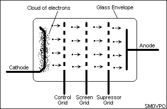
Here we see the pentode valve in all its glory with its electron movement. The typical characteristics for pentode and tetrode valves are the same as for a triode, but there are a few little additions:
| Function | Abbr. | Units | Typ. |
|---|---|---|---|
| Heater Voltage | Vh | Volts | 6.3 |
| Heater Current | Ih | mA | 300 |
| Anode Voltage | Va | Volts | 250 |
| Anode Current | Ia | mA | 48 |
| Control Grid Voltage | Vg1 | Volts | -4.5 |
| Screen Grid Voltage | Vg2 | Volts | 150 |
| Screen Grid Current | Ig2 | mA | 2.8 |
| Mutual Conductance | Gm | mA/V | 6.5 |
Notice how there is no voltage or current given for the suppresser grid (G3). This is because G3 would normally be connected to the cathode (0 volts) and does not have any current flow. Many pentode valves have the suppresser grid internally connected to the cathode to reduce the number of pins. It is quite possible to use the suppresser grid as another control grid for mixing purposes, but there is a (supposedly) better solution.
This is just an extension of the pentode and is primarily used for mixing. A mixer requires two (or more) inputs, so it needs two control grids. If G3 is used as a control grid then we have our basic problem back again, capacitance between anode and the new control grid G3. A 4th grid with a high voltage on it reduces capacitance, but also introduces secondary emission again, just like the tetrode. A suppresser grid G5 is therefore necessary.
A valve bottle may contain more than one valve. Example: ECC81 (12AT7) which has two triodes inside the one encapsulation. Each triode is independent of the other. Another example is the ECL80 (6AB8). This contains a triode and a pentode, but these are built vertically on the same cathode; "common cathodes". I will explain one method of using common cathodes later on.
Audio amplifiers can be constructed using almost any valve. Pentodes are most frequently used for power amplifiers, but either triodes or pentodes may be used for voltage amplifiers. Here is an example of practical Audio Frequency (AF) amplifiers using both triodes and pentodes.
Here is a basic and typical low power triode AF amplifier:
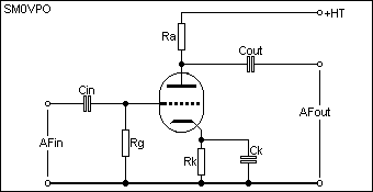
For the component values of the triode amplifier let us assume the valve characteristics are:
| Gm = 2mA/V | Vg = -4volts | Va = 200 volts | Ia = 2mA |
We are also going to use a supply voltage of 200 volts, so the anode voltage of the triode must be fixed at 100 volts so we can get +/- 100 volts output (0 - 200 volts) signal.
RESISTOR Grid to Ground - The grid input impedance is so high that even 1M0 will hold it at ground potential. Reduce the value if you wish to change the input impedance of the amplifier.
RESISTOR Anode Load - Ia = 2mA so we will run the valve a 1mA (signal = 0mA to 2mA).
R = E / I (basic Ohms law)
Ra = (SupplyV - AnodeV) / 1mA
Ra = 200 - 100 / 0.001
Ra = 100K ohms
RESISTOR Rk - Vg = -4volts w.r.t. (With Respect To) the cathode of the valve, so in this circuit we will lift the cathode 4volts positive w.r.t. grid. Cathode current in a triode = anode current, so back to Ohms law again:
R = E / I
Rk = GridV / 1mA
Rk = 4 / 0.001
Rk = 4K ohms
CAPACITOR Cin - Reactance at lowest input frequency must be less than 0.2 x input impedance of the valve (1M0 ohms). At 300 Hz this will work out to about 2500pf (2n5).
CAPACITOR Cout - Reactance at lowest frequency must be less than 0.2 x anode impedance of the valve (100K ohms). At 300 Hz this will work out to about 25000pf (25n).
CAPACITOR Ck - Reactance at lowest frequency must be less than 0.2 x cathode resistor Rk (4K ohms). At 300 Hz this will work out to about 1uf.
Here is a typical circuit for a pentode AF power amplifier:
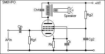
For the component values of the pentode amplifier let us assume the valve characteristics are:
| Gm = 5mA/V | Vg1 = -6volts | Va = 200 volts | Ia = 50mA | Vg2 = 150 volts | Ig2 = 5mA |
As in the triode, the maximum anode current is 50mA so will run the valve at half this figure - 25mA. This allows the signal current to vary from 0ma to 50mA. We will also run the screen at half the rated maximum figure - 2.5mA.
RESISTOR Grid to Ground - The grid input impedance is so high that even 1M0 will hold it at ground potential. Reduce the value if you wish to change the input impedance of the amplifier.
RESISTOR Rk - Vg = -6volts w.r.t. the cathode of the valve, so in this circuit we will lift the cathode 6volts positive w.r.t. grid. Cathode current in a pentode = anode current + screen current, so back to Ohms law again:
R = E / I
Rk = GridV / (anode current + screen current)
Rk = 6 / (25mA + 2.5mA)
Rk = 222 ohms
RESISTOR Rg2 - Supply voltage (200v) minus screen voltage (150v) = 50 volts. The screen is to be operated at 2.5mA so we are back to ohm's law again:
R = E / I
Rg2 = (SupplyV - Grid2V) / screen current
Rg2 = (200 - 150) / 2.5mA
Rg2 = 20K ohms
CAPACITOR Cin - Reactance at lowest input frequency must be less than 0.2 x input impedance of the valve (1M0 ohms). At 300 Hz this will work out to about 2500pf (2n5).
CAPACITOR Ck - Reactance at lowest frequency must be less than 0.2 x cathode resistor Rk (222 ohms). At 300 Hz this will work out to about 30uf.
CAPACITOR Cg2 - Reactance at lowest frequency must be less than 0.2 x Rg2 (20K ohms). At 300 Hz this will work out to about 0u3 (0.3uf).
CAPACITOR Chf - This is used to restrict the high frequency amplification of the stage to help prevent instability. Reactance at highest frequency must be greater than 3 x Ra (4K ohms). At 10000 Hz this will work out to about 20n (20000pf).
The transformer from the pentode valve anode must match the anode to the speaker, for example 3 ohms. The peak anode current is 25mA and the peak output voltage can be 100v, the anode impedance is therefore 4000 ohms. Impedance ratio is 1333:1 and turns ratio is about 36:1. Co-incidentally, a 250v-6v mains transformer will satisfy this need, but the laminations must be removed and re-inserted back into the former, but all in the same direction so that a small gap can be left. This gap prevents the 25mA standing current from saturating the transformer. A bit of typing paper will provide about the right gap. With 100volts at 25mA the transformer power rating will need to be about 2.5 watt (peak) or more.
If the above triode and pentode valves were constructed in the same glass envelope and shared the same cathode, then special biasing arrangements need to be made. Here is one solution:
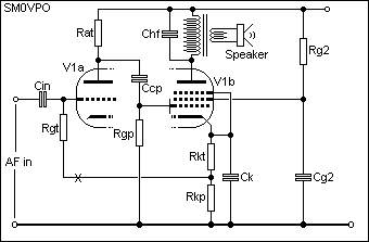
The cathode resistor must now provide a 6volt drop, but the total current though this cathode = Ia(triode) + Ia(pentode) + Ig2 = 1mA + 25mA + 2.5mA = 28.5mA. The largest control grid voltage is the pentode = -6volts so again ohm's law tells us we need a TOTAL resistance of:
R = E / I
Rkt + Rkp = 6v / Iat + Iap + Ig2
Rkt + Rkp = 6 / 28.5mA
Rkt + Rkp = 210 ohms
Now, the triode only needs 4 volts for the grid, so we connect the triode grid-leak resistor (1M0) to a 4volt tapping of the cathode resistor. The resistor Rkt is therefore:
R = E / I
Rkt = 4v / Iat + Iap + Ig2
Rkt = 6 / 28.5mA
Rkt = 140 ohms
Rkp = 80 ohms
In a single Superheterodyne (Superhet) receiver an RF amplifier may be used between the antenna and mixer stage. It could be used to amplify the RF signals from the antenna, but RF amplifiers are quite frequently used solely to provide additional tuning of the RF signal.
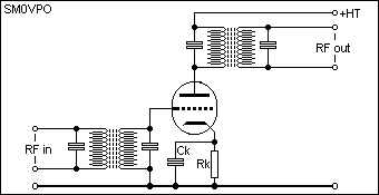
The tuned circuits in the anode and grid are often switched so that the receiver can operate on two or more different bands. Note that the anode coils have a few hundred volts on them so the switch would also carry voltages that 'hurt'. AGC could be applied to an RF stage although many constructors prefer to use a manual RF gain controls. Experienced operators often disable the AGC totally.
In a single superhet receiver an IF amplifier would be used between the mixer and the detector stages to amplify the incoming signals at another frequency, often for the second time. Fixed frequency tuned circuits are used in the anode and grid circuits and these are contained in screened 'cans' and are aligned when the amplifier is first tested.

Notice how the DC control grid voltage is not connected to ground via the input transformer. This is to allow Automatic Gain Control (AGC) to be used. Pentode valves are most often used in IF amplifier stages. The cathode decoupling capacitor may have a resistor inserted in series with it in order to reduce the gain. This would be needed in the case of high gain amplifiers using more than one valve in a single IF amplifier stage. Without this control the total IF amplifier may get an input from its own output resulting in instability or self-oscillation.
IF amplifiers, or any amplifier with AGC action, is normally a 'VariMu' valve type. This means that the control grid mesh is not wound in a uniform manner. The gap between successive wires in the grid spiral have a steadily increasing distance between them. This means that the grid will never properly switch the valve OFF (zero anode current) but the mutual conductance of the valve will steadily fall as the control grid becomes more negative. A variable DC voltage can be connected to the AGC input to control the amplifiers gain.
The DC voltage AGC voltage is normally derived from the detector (automatic) or a potentiometer voltage divider (manual). The DC voltage is normally fed via a resistor (Ragc) and decoupled with a capacitor to create a delay (time-constant) and to remove any residual AF from the AGC voltage. A residual AF signal on the AGC voltage would tend to remove the audio from the IF signal. Some receiving systems often get the AGC voltage from the receivers AF stages, especially when used in SSB receiving systems.
There are several basic oscillator circuits, having their own special advantages and disadvantages:
This is aboutthe most stable of AF oscillators and requires no inductors. This particular circuit will oscillate at about 800 - 1000 Hz. Choose polystyrene capacitors and the stability will be fantastic. Use ceramic capacitors and the frequency will vary with temperature, typically from 700Hz to 2000Hz.
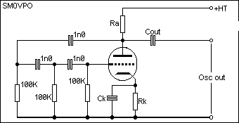
This is about the simplest oscillator that can be built using a triode valve. Frequency range is about 100KHz to 20MHz
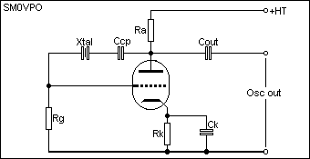
No adjustment of the frequency is possible. The grid-leak resistor (Rg) may have to be reduced in value a little, typically 47K - 100K ohms. This circuit will always oscillate at the fundamental frequency, even if harmonic crystals are used. This circuit should always be operated at a low power otherwise the crystal could become damaged. Capacitor Ccp is normally in the range of 20pf to 120pf, depending upon frequency.
This is perhaps one of the most simple and stable VFO circuits.
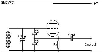
C1 is the tuning capacitor. C2 may be smaller or identical to C3. Examples of component values:
| C1 = 50pf | C2 = 10pf | C1 = 20pf | Cout = 5pf |
Replace the inductor with a crystal and insert a grid-leak resistor and you will have a very stable crystal oscillator. I have also used this circuit with a high-power pentode and crystal to achieve 40 watts of RF power out. Insert a choke in the anode, output taken from the anode (Via a capacitor) to an ATU.
Disadvantage, the feedback capacitors are in parallel with the tuning capacitor. This limits the max/min frequency ratio of the VFO to typically 2:1.
Here is a more traditional VFO circuit:
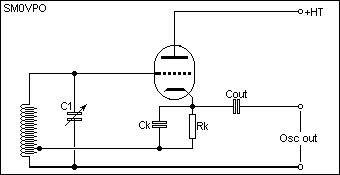
As you can see, this circuit requires a tapping on the tuned circuit inductor. The tapping should be about 5% to 10% of the total number of turns. The frequency ratio of this circuit is about 3:1 using a conventional tuning capacitor.
Well, I could continue with AM and FM detectors, power supplies, circuits to generate SSB, valve CW keyers, but I think the best thing is for you to go to some of the circuits I have presented on the homepage and compare what you have now learned. After all, this is only an introduction and not a reference book!!
Valve (tube) data, courtesy of Trevor Gale.
Antique Electronic Supply Company stocks thousands of valves and components.
Have fun, de HARRY, Lunda, Sweden.