OPERATIONAL AMPLIFIER BASICS
by Harry Lythall

Introduction

The Operational Amplifier (Op-Amp) was developed many years ago for analogue computing. This was in the days when the output information from a calculation was readable with a simple voltmeter. Fortunately for us, the Op-Amp can be misused for a huge variety of functions. In this page I will attempt to show what the Op-Amp is and a few uses of it.

What IS An Op-Amp?

Basically, the Op-Amp is nothing more than a differential amplifier that amplifies the difference between two inputs. One input has a positive effect on the output signal, the other input has a negative effect on the output. The component circuit symbol is:

For clarity, the power supply terminals to the amplifier chip are not usually shown, except on detailled circuit diagrams. The Op-Amp requires two power supplies; a positive voltage supply and a negative voltage supply, both with respect to our circuit ground/Earth/chassis connection.

The theoretically perfect Op-Amp has an infinite voltage gain, an infinite bandwidth and infinite input impedances. In this way it just senses an input voltage level without actually interfering with that voltage in any way. The perfect Op-Amp also has a zero-Ohm output impedance. It may therefore be used to drive heavy (in electronic terms) circuits.

A Practical Op-Amp

The practical Op-Amp is far from perfect, but the more you pay then the better the Op-Amp you get. The circuits I will give you in this article can all be built and used using the LM741 Op-Amp. Here you can find the datasheets for

A typical operational amplifier has input impedances of 100M-ohms, 1-ohm output impedance and will drive up to 20mA of output current. Supply voltages may be as high as +20V and -20V (total 40 volts from +ve supply to -ve supply). The typical voltage gain/bandwidth of a normal Op-Amp is about 1 000 000. This is to say that at DC it will have a voltage gain of one Million, but at 1MHz it will only have a voltage gain of 1.

To understand a little more of what is inside the chip, here is a much simplified circuit diagram.

The circuit will function quite well with the component values shown, should you feel the need to built the device. In the real Op-Amp, the silicon diode biasing and current limiting resistors are constant current supplies that enable the device to operate at low supply voltages.

Now you have a little information about what the device is, let us take a look at what it can do.

Basic Function

The basic function of the Op-Amp is to multiply a voltage level by the gain of the amplifier. If you were to couple a DC level of +1v into the + input of our Op-Amp then the output would be 1v X 1000000 or one Million volts. The output, however, cannot exceed the supply voltage, so the output will be +20v DC.

If you were to couple a DC level of +1v into the - input of our Op-Amp then the output would be -1v X 1000000 or MINUS one Million volts. The output, however, still cannot exceed the supply voltage, so the output will be -20v DC.

If you were to couple a DC level of +1v into both the - and + inputs of our Op-Amp then the output would be (-1v X 1000000) plus (1v X 1000000) = 0v.

In other words, both inputs act on the output simultaneously and the output is the sum of both input functions. If both inputs are identical then the output should always be zero. This is a good test for an Op-Amp. If you connected both inputs to the same input, then the output SHOULD be zero volts. In reality, there are small differences in the circuit's characteristics and components, this will result in a small "offset" voltage.

The numbers beside the Op-Amp symbol are the chip pin numbers for the LM741.

The offset voltage can be corrected on several Op-Amps by an internal circuits known as "offset null" which means that the offset voltage can be trimmed out.

In most Op-Amp applications this function is not necessary, but in very accurate systems, such as instrumentation, the function can be very useful.

The Op-Amp As A Comparator - Logic

One of the most basic Op-Amp functions is the voltage comparator. Here the two inputs are used to compare two different voltages. If the input to the + input is greater than the input to the - input then the output will be 1000000 times the difference between the two inputs.

Example, if the + input were +3.2vDC and the - input were +3.215vDC then the output voltage will be 1000000 X the difference between the two inputs, or 1000000 X -0.015vDC = -15000vDC. Again, the amplifier cannot output a voltage beyond the supply voltages so the output will become -20vDC.

Wow! This opens up a few possibilities. The gain is so high that the output can never be practically anything else but -20vDC or +20vDC. This is a good input circuit to CMOS and other digital equipment. Just change the supply voltages to match. It can also interface directly to an RS232 computer input if the supply were just + & - 10vDC. RS232 requires a 20mA current limit capability, so the 741 Op-Amp is ideal. The Hamcomm interface uses just this effect to interface an analogue signal to the computer so radio amateurs can interface a radio receiver to the PC.

The basic voltage comparator can also have many other uses, for example, as a battery under/over voltage indicator.

Here, the input voltage to your precious VHF transciever can be monitored by a simple device to give you an idea as to the battery condition. The 13.8vDC input is regulated by a Zener diode (6.8v works fine) and the resultant 6.8vDC is then presented to the -ve input of the Op-Amp. This will drive the Op-Amp output to the -ve supply voltage, which in this case is ground (0v). The input voltage is also divided by a 50K preset potentiometer and fed into the + input of the same Op-Amp. As long as the 50K preset delivers more than 6.8vDC then the output of the Op-Amp will be high and equal to (almost) the 13.8vDC input. If you want to reverse the sense of the device then just reverse the + and - input to the Op-Amp.

The DC output from the 50K preset potentiometer will vary in sympathy with the 13.8vDC input to the whole circuit. The DC voltage across the Zener diode, however, will be a constant, quite independant on the input voltage. Assume the 50K preset is set to mid-position then the pot will deliver 13.8/2 = 6.9v to the Op-Amp + input. The Op-Amp will therefore always deliver a high voltage from it's output and the LED will be illuminated. If the input fell below 13.6vDC then the preset will deliver less than 6.8v to the Op-Amp and the Op-Amp output will change from High (13.8v) to Low (0v). A voltage warning indicator.

The Op-Amp comparator can also be used in many other applications where voltages vary, for example, the basic CR time-constant circuit. In this example, I have chosen to make a simple timer circuit.

When the switch S is pressed and released, the capacitor C will discharge, then begin to charge through R. The voltage across C will start at 0v, so the output from the Op-Amp is also Low (0v). As soon as the capacitor charge rises to more than 6.8v then the + input to the Op-Amp is greater than the - input and the Op-Amp output will suddenly switch High (12v) and the LED will light. In this circuit you may, of course, replace the 470R and LED for a small relay. Any relay capable of switching from just 20mA will do the job.

Ok then, so now you know all about using the Op-Amp as a voltage comparator and some of the ways it could be used. It is probably time to start using the Op-Amp in some analogue circuits.

The Op-Amp As A Comparator - Analogue

The basic Op-Amp gain is for too high to be of much use in analogue circuits without some form of control. That form of control usually comes in the form of "negative feedback". This means simply connecting all, or a part, of the Op-Amp output back to the - input.

Here we see that pin 6 of the Op-Amp is coupled directly back to pin 2, so that 100% of the output voltage is coupled back to the - input of the Op-Amp. Now we have applied 100% negative feedback. If any voltage is applied to the + input (pin 3) then the Op-Amp will only become stable if the output voltage is the same. If the output is too high then - input is higher than + input and the output will fall. If the output is too low then - input is lower than + input and the output will rise. The only stable condition that can exist is if the + and - inputs are the same voltage.

If you now vary the 50K potentiometer then the Op-Amp output will follow the input voltage from the pot. The advantage here is that any load placed on the Op-Amp will not affect the voltage since the Op-Amp controls it. Any error will be fed back in the opposite polarity and cause a correction. This circuit is a simple low current (20mA) variable voltage generator. You can increase the output current capability by adding a transistor for the Op-Amp to drive.

Here we have added a single transistor buffer stage. If the Hfe of the transistor was 100 and the Op-Amp can deliver up to 20mA, then this PSU circuit would handle up to 2-Amperes. Naturally, the transistor should be fitted to a heatsink and should be capable of handling that sort of load current. You will also see that I have taken the liberty of taking the reference voltage from a Zener diode. Now our power supply unit will be as well regulated as the Zener diode.

The power transistor will drop 0.7v between Base and Emitter (1.4v for a power Darlington transistor) which would otherwise lower the output voltage of the complete PSU. I have connected the - input of the Op-Amp, not to the Op-Amp output, but to the output of the regulator transistor. The circuit functions exactly as before, but the result of the 100% negative feedback will be to maintain the output of the transistor TR at the correct voltage. The output of the Op-Amp may be a volt or two higher than this; whatever is needed to control the transistor.

In reality, this circuit would be a little dangerous to use withou some form of current limiting, but that is outside the scope of this article. There are circuits elsewhere on my homepages.

One other small point, all devices generate noise. The Op-Amp is no exception, but in the above circuit the negative feedback will remove all traces of noise from the output of the PSU that are generated WITHIN THE FEEDBACK LOOP. The 50K pot and Zener diode lie outside the feedback loop. The 50K pot will not generate much noise, but the Zener diode is a very noisy device. It should be decoupled with a large electrolytic capacitor.

Another point here is temperature stability. A 15v zener diode will have a voltage variation of about 25mV for every degree Centegrade. A 10 degree rise in temp will therefore cause the full-voltage output from the PSU to vary by 1/4 of a volt! To overcome this we can modify the circuit to use the gain of the Op-Amp. We know that high-voltage Zener diodes have a +ve temperature coefficient and low-voltage Zeners have a -ve coefficient. A 5.6v Zener has a temperature coefficient of about 0v per degree centigrade. So let us substitute the 15v Zener with a 5.6v Zener. Now let us modify the circuit so we can still have a 0-15v variable PSU.

All I have added is R1 and R2 which form a voltage divider. The feedback loop now has a bit of gain, equal to (R1 + R2) / R2 which is a gain of only 2.7857. The reference can now vary from 0 to 5.6v and the maximum voltage available is 5.6v X 2.7857 = 15v (welllll..... 15.6v ... maybe a little over, but who cares?).

If the Zener generates 5.6v and the voltage pot is set to maximum, then the + input of the Op-Amp is +5.6v. This will drive the output of the Op-Amp high, until the - input of the Op-Amp (pin 2) is also 5.6v. Pin 2 is connected to the junction of R1 and R2 and this can only become 5.6v if the right-hand side of R1 is 15.6vDC. Our PSU now works and has a very good temperature stability.

Audio Amplifiers

The Op-Amp makes an ideal audio amplifier with very few external components. With an output current of up to 20mA then it can also drive headphones and even high-impedance speakers, eg. 50 - 80 ohms. To use the Op-Amp for linear (undistorted) audio applications we always need to use negative feedback. It is the negative feedback that "tames the wild beast". With an "open loop" voltage gain of over 1000000 times then we do need to "tame" the amplifier.

R1 and R2 again control the voltage gain of the amplifier and the gain is equal to (R1 + R2) / R2 and the gain may be set to anything practical within the scope of the Op-Amp. Bear in mind the gain/bandwidth characteristic of the Op-Amp. If you wanted the amplifier to have a flat response from 0 - 20KHz and the Op-Amp gain/bandwidth was 1000000, then at 20KHz the open loop amplifier gain cannot be greater than 1000000/20000 = 50. If you wanted a flat response from 0 - 20KHz with a gain of 200 then you should use two amplifiers with a total voltage gain product of 200. Audio test signals through the amplifier should be sinusoidal, something like this:

The amplifier shown has a frequency response of 0Hz to "somethingquitehigh" and is limited only by the Op-Amp gain/bandwidth characteristic. The input resistor Rin can be typically 1M0 and just references the + input to ground (0v). If you wanted a specific input impedance then change Rin to suit the input impedance you want. In real life you would also want to isolate the input and output from any DC component. This would be done with capacitors:

The reactance of the capacitors should be at least 0.2 x the input or output impedances at the lowest operating frequency. For example, Rin = 50K and the lowest frequency we wish to amplify is 20Hz, then the reactance of C1 shall be 10K at 20Hz, which would be about 0.8uf. If the output were driving a 72-ohm headphone then C2 reactance shall be 14.4-Ohms at 20Hz, or about 560uf.

This amplifier would be quite fine if you had both + and - 20v DC supplies, but in most applications we are not so fortunate. To modify the circuit to operate from a single supply, we have to move the amplifier DC operating point away from 0v to something else. Add a couple of 1K0 series resistors to divide the single supply voltage. If we had a single supply of +20 volts available, then the new operating point would be 1/2 of that = 10vDC.

Naturally, the two 1K0 resistors shall be decoupled to remove any trace of audio ripple, using a BIG electrolytic capacitor. The reactance of the capacitor shall be 0.2 x R2 at the lowest operating frequency. If the two 1K0 resistors were NOT identical then the amplifier would distort at high signal levels:

All the coupling and decoupling caps values discussed so-far are MINIMUM values. If the capacitors are larger then the AC characteristics of the amplifier will only improve a little. If they are too large then it may take a few seconds (or minutes) for the amplifier to stabilise when you switch ON the power.

The AF amplifiers discussed so-far have the input signal fed into the + input which means that the output signal is in the same phase as the input signal. But what if we want the signal to be inverted? Easy, change the original configuration to feed the input signal into the -ve input:

In this event the input resistor Rin that sets the input impedance is also the R2 feedback resistor. The gain of the stage will also be reduced by 1. The voltage gain is now R2/R1 which means that an amplifier voltage gain of less than 1 is now possible.

Another usefull point with this circuit, the output and inputs are 100% out of phase. The + input is referenced to 0v (ground) and so the -ve input MUST also be 0v. There will also be NO SIGNAL at the - input pin. This point in this circuit is called a "Virtual Earth".

Audio Power Amplifiers

Power = Volts X Amperes. So to get an AF power amplifier we must have both volts and current. We have already seen how to build a voltage amplifier, now let us give it a little current capability. We can do this by simply adding a pair of power transistors, one to give positive current, the other to give negative current.

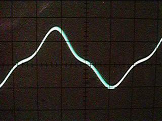
It is quite simple and this particular amplifier will deliver over 20-watts RMS (40-watts Music Power) into a 6-Ohm speaker. It will sound like crap, but at least the power is there (great for RAP music!). Notice how R1 has been moved. In this way the distortion generated by the power transistors will be fed back to generate an "anti-distortion" signal at the output of the Op-Amp. If the voltage gain of the amplifier is set quite low, for example X10 maximum, then the sound of this circuits is quite acceptable. But if you put your head inside the speaker, or increase the gain, then you will hear a very unpleasant distortion at low volume levels. This distortion is called "crossover distortion" and is caused by the transistors not conducting until the signal level has exceeded 0.7vDC. It looks like this on an oscilloscope:

The cure, of course, is to make the transistors conduct a little current when they are idle. The simplest form of conduction bias would be to add resistors and diodes.

The resistor R+ and D1 provide a bit of current into the base of the NPN transistor. D1 ensures that the DC voltage is the output of the Op-Amp plus 0.7v. R- and D2 do the same at the opposite side for the PNP transistor.

Audio Amplifier Limitations

Let us go back to our basic Op-Amp AF amplifier for a few moments, both the circuit and all the internal "gubbins":

and

Remember that the Op-Amp may operate from as little as 5v and as high as 40 volts. This gives rise to some form of design conflicts, at least with the cheaper Op-Amp chips. At low signal levels they can distort; crossover distortion generated within the chip. If you want an output signal of, say, +/-10v then there may be no problem at all, but a small high-gain pre-amplifier with an output in the region of 0.1v RMS could suffer terrible crossover distortion. The "cure" for this is to either reduce the gain and/or add a bit of bias current to the output stage.

I have now added Rbias which makes one of the output transistors (BC557) conduct permanently. This effectively converts the output stage to a single transistor Class-A amplifer, the other (NPN) transistor never being used.

If you do not wish to muck about with transistors in conjunction with an Op-Amp then choose a "Power Op-Amp" such as the LM2020 which already has the power transistors built-in. This Op-Amp will provide 20 watts of audio. You can even use it to drive motors and lamps. This amplifier must be mounted on a heatsink.

Frequency Response

Now you know what an Op-Amp is all about and how it can be used to make amplifiers, let us consider the limitations of frequency response. I have already introduced the concept of "Unity Gain/Bandwidth" (UGB). So let us explore this a little more.

Imagine for one moment that an Op-Amp had a Unity Gain/Bandwidth of 1000000Hz and we used resistors to set the amplifier voltage gain to 190 and then 20. What would the actual frequency response be? This graph shows you exactly what will happen.

With a voltage gain of 190 set, the amplifier will have a gain of 190, but ONLY up to that frequency where the open-loop gain of the Op-Amp reduces to 190. That point would occur at about 6KHz. Not very good for Hi-Fi reproduction! But if we were to reduce the voltage gain to just 20 then the frequency response would extend to 50KHz. If we needed an amplifier to have a gain of 190 then we would be far better off to have two cascaded amplifier; each with a voltage gain of just 14. The total gain would then be a little over 190 and the frequency response would be DC to over 70KHz.

Frequency Response

But is UGB the end of the limitations story? No! Operational amplifiers have another property called "Slew Rate". This means that if the input waveform were to be a square-wave then the output would not change instantaneously. It would take a finite time for the output to change state.

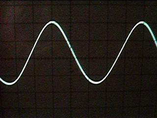
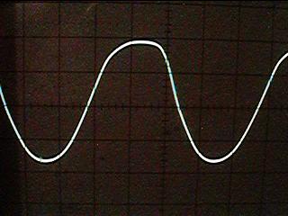
If this slope were shallower than a part of our signal then the signal waveform will distort. If the same waveform were reduced in amplitude then the signal slope would also reduce. This means that the Op-Amp's "slew rate" would affect high-level signals more than low-level signals. Consider the following two output sine-waves with respect to the slew-rate (shown in RED).

In the first waveform, the signal amplitude is high, so the slope is steep; steeper than the slew rate of the Op-Amp can follow. The waveform will therefore become distorted. The second waveform is of exactly the same frequency, but the signal amplitude is low. The slope of the waveform is therefore less steep than the slew rate of the Op-Amp, so the waveform will be undistorted.

In reality, the Slew rate characteristic of an Op-Amp will only affect signals of a very high frequency, or waveforms having a very steep rise and fall time, for example, square and sawtooth waveforms. For general audio work up to about 30KHz you can normally forget about this effect. The slew rate of an Op-Amp may complicate matters if you try to drive fast logic circuits, such as the 5400 and 7400 series. If you need to drive TTL circuits from Op-Amps then try to choose a logic gate that has a "Schmitt" input function. CMOS gates tend to be a bit more forgiving so you can usually get away with driving them directly from Op-Amps.

Active Low-Pass Filter

The high input impedance of the Op-Amp makes it especially usefull in filter design. Simple RC filters are good, but in order to take an output signal from them you need to load the filter. It is the load that "cocks up" everything. Your load circuit may be resistive, that will affect the responses of the filter. If your load is capacitive or inductive then you have little chance of predicting the outcome with any form of accuracy. So, let us consider the basic Low-Pass filter:

At the frequency of calculation, the output signal will have fallen by 50% of the voltage, or -6dB if you prefer decibels. If you double the frequency then it will have fallen by another 50% (now 25%). Another usefull reference point is the output signal falls by a further 90% every frequency decade. To all intents and purposes, the loss of the filter is zero at F/2. The filter has no gain, in fact, any load at all will cause it to have a loss at all frequencies. This is what we are going to cure first.

( or to be more conventional )

The Op-Amp has simply become a high-impedance buffer stage and has also given the filter a little gain by virtue of (R1+R2)/R2, or R/Rgain in the more conventional circuit. The output impedance is almost zero ohms.

The Op-Amp really "earns it's corn" when you want a little more that 6dB/octave (20dB/decade) rolloff. You could simply cascade two single-pole filters, but inacuracies can enter when one filter is a load for the next. This filter is a 2-pole filter having a rolloff of 12dB/octave (40dB/decade), which in real terms is 25% of the original signal level:

Notice that the turnover formula has changed a little. The 6dB point has now become a 12dB point; the new 6dB point is somewhat lower in frequency, so the 1 in the top line of the formula has become 0.7071 instead. This filter gives a unity gain up to the point it begins to "turnover" - about 0.5/(2 pi R C)

Active High-Pass Filter

The active high-pass filter is almost the same as the low-pass, but the C and R are exchanged in the circuit to give the opposite response curve. First, the basic high-pass circuit element.

Again, the turnover frequency for the single-pole filter is 1/(2PiCR) and now we shall buffer it with the Op-Amp.

The basic response is still 6dB per octave (20dB per decade) which may not be too usefull for general work. To all intents and purposes, the response is flat from 2/(2PiRC) upwards. Adding an extra RC circuit to make a 2-pole filter will increase the rolloff slope to 12dB per octave.

The The losses at 1/(2PiCR) have now increased from -6dB to -12dB so the rolloff point is now 1.41/(2PiRC). I must state here that this only applies for a unity voltage gain (1). To get other voltage gains complicates the formula and they can become quite complex.

Active Band-Pass Filter

This is easy. Use a Low-Pass AND a High-Pass in cascade.

Active Rejection Filter

In many application you need to pass a complete band but with a filter to reject just one single frequency. There are many circuits for this, but here is one that I find so simple that even I understand it and I can remember the formula!

The notch frequency is 1/(2PiRC). The "Gyrator" circuit uses two Op-Amps in a novel circuit where one amplifier inverts the effects of a capacitor which then behaves as an inductor. But I think this has now gone beyond the scope of an article on Op-Amps. But here is the circuit, anyway.

This is one of the circuits that remains firmly planted in my memory, but the brain-failure has extended to the formulas - Sorry! The rough order-of-magnitude is that R is 10K and C is 10nf for somewhere in the middle of the AF band, probably about 1.5KHz. This would imply that 1/(2PiRC) would be the formula, but don't quote me on that. The resistor Q would be about 100K for a bandwidth in the region of about 10Hz or so. Gain is 1 although the output impedance from Out1 is quite high, so an Op-Amp buffer would be needed here.

References

This is about all I wish to write on this subject. If you are interested in further reading then I suggest you take a trip to your local library. There are several educational Op-Amp books that you may find of interest:

The ARRL Handbook For Radio Amateurs is rather good and easy to understand, but it is a little rudimentary. Assuming you know nothing, you assimilate all the Op-Amp section in one "sitting" on the toilet.

Electronic Circuits (Discrete and integrated) Donald L. Schilling & Charles Belove published by McGraw-Hill International is a real goldmine but tends to be a little "heavy" when it comes to mathematics - I keep my copy in the toilet so I am never short of reading material.

The IC OP-AMP Cookbook" is published by Sams & simply OP-AMPS published by Newnes press are both well worth reading. They contain a lot of useful information for all levels of knowledge. If you seriously wish to learn more, or have an Op-Amp reference data handy, then these are the books for you.

If you want an on-line resource for active filters then you could visit http://www.electronics-tutorials.com/filters/active-bandpass-filters.htm or http://www.filter-solutions.com/active.html where you will find loads of information, although a lot of it is designed to sell filter design software.

Best regards from Harry Lythall - SM0VPO, Lunda, Sweden

Return to INFO page