
I have been playing with my new FT-840 on-the-air. Although I have had few contacts, I have tried reducing the RF Power level to 5 Watts and still got reasonable reports; typically 5-4 and 5-5. When I was in Spain I spent hours to get my first contact using my little X1M, and then the reports were very bad, typically 2-3 and 3-4. Really hard work. So what is the difference?
I believe it is the speech processor!
I have been spoilled with my old FT-101ZD and the new(er) FT-840, where I can flick a switch and compress my audio, play with the mic gain, and adjust the audio to suit the conditions. The FT-840 has compressor ON/OFF and a MIC-GAIN. The FT-101ZD also has a compression level control, so the older rig is more versatile. It is just a pity that the FT-101ZD weighs 17kg! For QRP you really NEED some sort of advantage, so here is my planned speech processor. I want to make an external unit that I can use both with the X1M, and the FT-840. Now Harry starts learning about speech processing for HF communications :-)
The microphone that was supplied with the X1M was a "speaker/mic" using an Electret condenser microphone. The X1M does not have a speaker output from the microphone socket, so the speaker is useless. To add insult to injury, there was not even a hole in the microphone case for the microphone! I drilled a 3mm diameter hole over the microphone element and the reports became clear and clean audio, but still extremely weak.
The X1M has a 4K7 resistor from the 7 Volt supply, so I thought I would use that power source to power a small BC547B amplifier built into the microphone. I also replaced the electret microphone for a Karaoke dynamic (magnetic) microphone. This gave much better results and more people answered me. I also saw that the average RF level rose to about 500 mW.
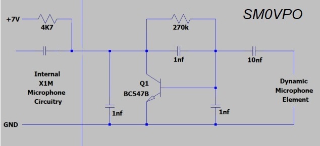
This gave the X1M a new life. But despite the use of 1nf capacitors around the transistor, when the rig was close to the vertical groundplane antenna, RF found it's way into the microphone circuit and gave loads of strange noises. The X1M has a 3.5mm stereo socket for the microphone input, but it is cheap, made in China, and if you push in a plug that is microscopically larger than the original microphone plug, then the contacts get bent. There is no "springiness" in the contacts. This creates a poor ground connection, intermittent connections, and makes the rig useless. I am going to drill a hole in the rear apron and fit a much more robust connector, with decent ground connections, and I am sure I can use my Karaoke microphone. However, wouldn't it be nice to have a speech processor? At the moment I STILL don't have any workshop that you can call a workshop, so everything has to be done theoretically.
Maybe NOT so theoretical? I was recently given a copy of LTspiceXVII. I used SPICE simulations many, many years ago, but I never went very far with it. Now I have started simulating circuits with LTspiceXVII, and the new Proteus 7.7 PCB layout means I can do a lot with my little laptop, sitting on the bed beside Maj-Lis, while she watches Midsommer Murders" on the telly.
Before I go any further I should perhaps give a bit of information about that which I am trying to achieve, as well as my thoughts behind this project. I shall begin with a little history.
From 1999 to 2009 I did a lot of multimedia work and produced about 750 educational videos for Ericsson internal use. The object was to show installers and engineers around the world the installation quality that was expected, no-matter which country the installation took place. I learned a lot. My responsibilty was to research installation methods, create a storyboard, speech manuscript, read it, then process the audio file for the video clip.
One of my "funny internal review" films had a short video clip clip posted on YouTube. The object was to make reviewers look forward to watching my videos. They would be cleaned up before publishing. This should never have been posted outside the department, but it was.
If the target audience is sitting at home, no kids around, possibly headphones on, then all I needed to do was to "normalize" the sound so that the peaks were hitting 99%. The un-processed average audio level is therefore about 5% to 10%. No compression is needed, other than clipping off the odd click, pop and other "abnormal" sounds that come out of the mouth, before normalising it. This gives a lovely clear, crisp audio with a wide dynamic range. Classical music, for example, has no compression whatsoever. If you listen to Joseph Hyden's "Surprise" Symphony No.94 then you will know what I mean. Hyden relied on the fact that that the audience had to listen more intensely to hear the quiet bits. Then he blasted them with the timpany - the surprise.
When a viewer is in an office environment, a total lack of compression can cause the odd word to be lost. One word can change a whole meaning. Consider "The tiger will make a hearty meal of tourists", or "The tiger will make a hearty meal for tourists". In an office environment, with a little background noise, you have to have a little compression to be sure that all the speech is heard. This is light background noise. Editing the audio therefore will require clipping of the pops and ticks, cutting out the odd teeth-whistles, then adding just a little compression. The object is to reduce the difference between the peaks and the average level, and bring the average level up to about 15% to 20%. If you increase the average too much then the speech can sound un-natural.
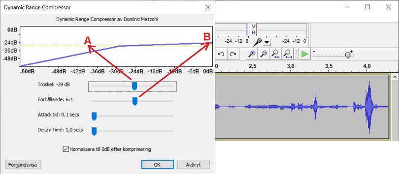
The compression THRESHOLD (A) is like adjusting your MIC-GAIN control.
The compression depth (B) is like adjusting your compression level.
After compression the audio is normalised to about 95%.
In a conference room, cinema (remember cinemas?), or large indoor area, then people talk, whisper, rustle papers, play with the OHP controller, or even open a window to let in outside noise with the fresh air. In this case the audio should be a little more compressed so that everyone has a fighting chance to hear what is said. I would bring the average level up to about 25% for this audience. This type of environment is also that which the HF radio should ideally have. HF receivers have a background noise level, so a little light processing is all that is needed. It is similar to light makeup on your wife's face. If you notice it then it is too much. See my exmple #3 below.
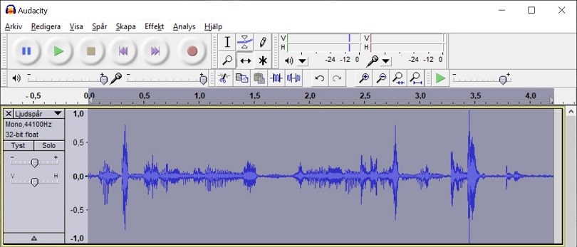
If a multimedia target group is in a public area, a shopping mall or airport (before COVID-19) for example, then the listeners will be used to heavy compression. Heavy compression is needed to the average audio level can compete with screaming kids, floor-cleaning machines and 1001 people chatting. This is called "babble-noise". My videos for this environment used quite heavy compression, where the average level was around 40% of the peak level. At this sort of level there is no way you can make it sound natural, but it should not be offensive or irritating. I used this level of compression for the "Paris Walks" when GPS and GSM were combined to give a guided tour, including the Eifel Tower.
Hamradio however, is a little special, where QRM and weak signals can overpower your speech, especially if you are running a QRP station. In this event you may occasionally need quite heavy compression. This project is designed to allow a variety of compression levels, up to very heavy.
Having said all this, the best speech processor is your own mouth. No amount of speech processing can improve the way you speak. Speak slowly, clearly, and try to vocate the vowels. One exercise I have done is to analyse how other people speak. Slow, slightly deep tone and as constant as possible. Most amateurs with whom you speak do not speak your native language, so try to use simple words. The English are notorious for using obscure, acromatic, cabalistic or lesser-known words.
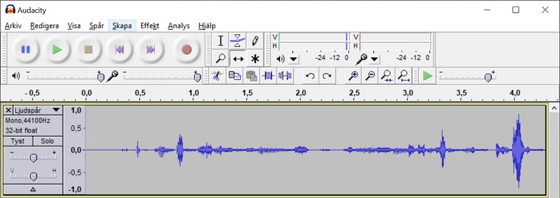
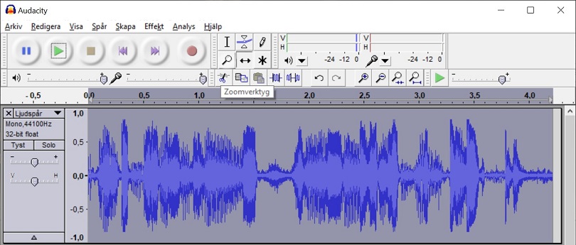
If you want to know how these examples sound, then click the play button on these links. All three examples are peaking at about the same level, 95% or so, it is just the average audio power level that changes.
4 - No compression ("thin" audio)
3 - Light compression (normal)
2 - Heavy compression (sounds compressed)
1 - Excessive compression (sounds annoyingly "harsh")
If you want to take the analogy of a lady's makeup, when compared with audio compression, then here is an example that illustrates the point I am trying to make:

The point is that a little compression in communications will increase the average volume, but the listener will not be aware that any audio compression is used, unless you need to get your voice out of the noise.
Here you can see the circuit was drawin in SPICE, but the components are numbered in the order I entered them. Sorry!! Note that there is no R11.
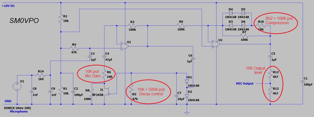
V2 is an audio signal generator, which at the moment is set to 10mV AC (no DC bias). C8, C9 and R14 are the customary RF filtering. This is fed into the OpAmp (LM358a) non-inverting input via C3. R2, R1 and C2 are the supply voltage divider components to give me a 5V DC reference voltage for the whole processor. R4 is just a DC reference to the positive-acting input of the OpAmp U1. R4 sets the input impedance of the speech processor and can be anything, from 100 Ohms to 470K.
The AF gain of U1 is set by R3 and R6. R6 is a 10K potentiometer in series with a 100R resistor, which is the MIC-GAIN potentiometer, mounted on the front of the unit. The MIC-GAIN potentiometer is grounded through the BF245B Field-Effect transistor, which is normally almost a short-circuit under no signal conditions (Gate to source voltage is 0 Volts).
The output of U1 is coupled through C6 (DC-block) to D1 and D2. These diodes rectify a negative DC voltage from the amplified microphone input. This negative DC voltage, applied to the Gate of J1, will cause the FET to increase it's Source-to-drain resistance. Since J1 is in series with the MIC-GAIN potentiometer this will have the effect of reducing the gain of the amplifier. C7 charges to the DC voltage (+ve terminal to ground) to store the gain-control voltage. R5 discharges C7 slowly when there is no signal, so the microphone amplifier gain will increase if you stop speaking. This gives about 500ms recovery time. If you want to add a DECAY control to the processor then R5 can be a 10K resistor in series with a 500K potentiometer.
The microphone amplifier will therefore give a reasonable output level with an input of anywhere from 3mV to 100mV, which should be ideal for electret microphones, or dynamic microphones. The output level will vary from about 500mV to 900mV over this full range. It will tolerate up to 500mV from your microphone, with only a 50mS "pang" when you start talking. But this is a good reason for having a MIC-GAIN control.This completes the "constant-volume microphone amplifier".
With my little X1M running just 5 Watts I really want a bit more "punch". A simple constant-volume amplifier will not do this as you will still have the same dynamic range. So next we add a compressor.
U2 (LM358b) is another amplifier, but the gain is set to 2. The positive-acting input it V/2 and the gain is set by R9 and R7. This time I put a pair of back-to-back diodes in the negative feedback loop. Each diode is two 1N4148 diodes in series with R10. If the output level from the amplifier exceeds +/- 1.4 V AC then these diodes conduct and the 10K resistor, R10 bypasses the 100K resistor R7. This has the effect of reducing the gain on peaks.
The voltage drop across a diode is NOT constant; it varies with current and follows a logrithmic curve. This makes the waveform look (and sound) more rounded, instead of hard-clipped. You can replace R10 with a 2K2 fixed resistor and a 100K potentiometer in series to give you a variable compression level. Alternatively you can use a 22K fixed resistor and a 50K potentoiometer in series to replace R9.
C5 is a DC-block to couple the audio to the X1M microphone input. R12 and R13 are in reality a 10K potentiometer for OUTPUT LEVEL. I could not find a SPICE model for a potentiometer, but I don't know if it is possible to simulate one. Whatever, I just used two fixed resistors to simiulate the output level pot.
Here are some typical figure for output level vs input level:
| Input | Output | Microphone |
|---|---|---|
| 1mV | 320mV | |
| 2mV | 630mV | eg. Ribbon microphone |
| 5mV | 680mV | |
| 7mV | 730mV | |
| 10mV | 800mV | eg. Electret condenser mic |
| 15mV | 810mV | |
| 20mV | 815mV | |
| 25mV | 820mV | |
| 30mV | 822mV | eg. Dynamic microphone |
| 50mV | 828mV | |
| 100mV | 840mV |
Microphones can have a very wide range of output levels. the ribbon-type only has about 2mV, but this is normally a low impedance and often uses a transformer to increase the output impedance and the voltage level. Electret condenser microphones have an in-built FET amplifier and these can give typically 10mV with normal speech. You can get more if you "talk them up" but you end up blowing on the mic and this sounds really bad. Electret microphones also have a very wide frequency response, up to several 10's of kilohertz. Anything above about 4kHz is not much use for communications. Dynamic microphones are less susceptable to "crackle" and they sound a lot more "full", but this is only my experience.
In "normal" use it is not such a good idea to have a lot of compression. With this little compressor I am hoping to make my little X1M come up out of the noise, but if the receiving station has a strong signal from me then I can always back off the gain and compression, using the compressor to limit peaks. Very little compression is always more pleasant to listen to, but when there is a lot of noise or QRM it can hopefully make myself heard.
The project is built on a single-sided PCB measuring 6cm x 6cm. All holes are 1mm Diameter, but 0.8mm works fine. Here is the PCB foil pattern, viewed from the copper side. If you can read the text on the copper side then it is the correct way round.
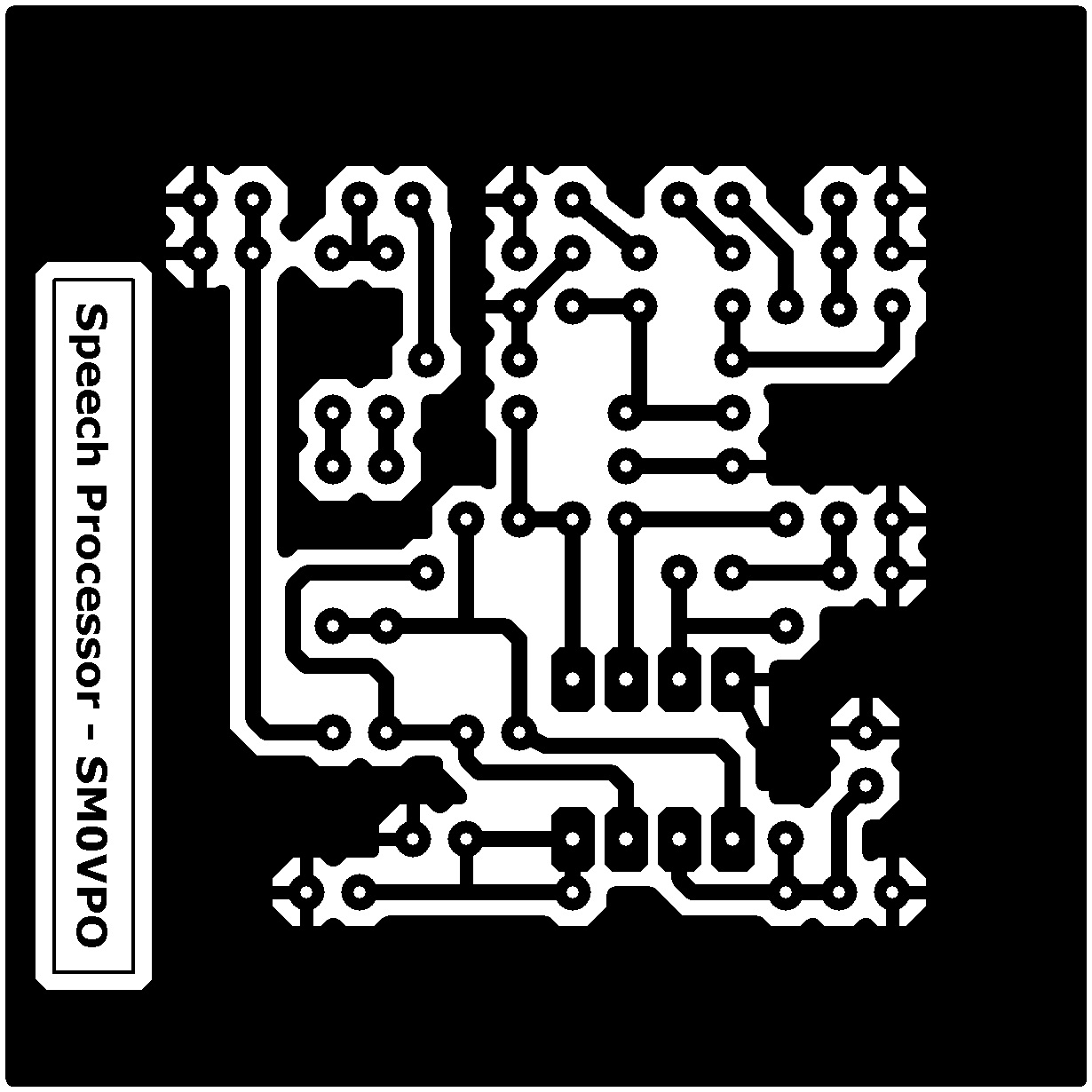
Here is the component overlay. This is viewed from the component side of the board, with the copper shown as an "X-Ray" picture under the components. As you can see, there are no wire links to be fitted. I suspect I may have to choose the components to fit the holes, at least the electrolytic cpacitors. But my stocks of electrolytics are nearly all 2.5mm spacing.
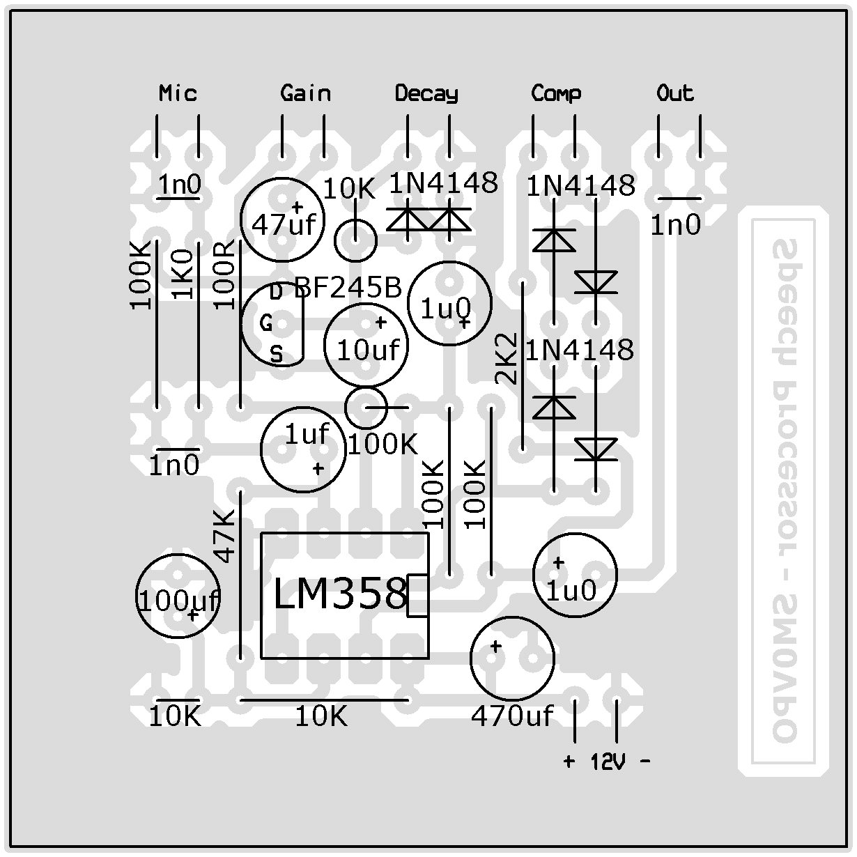
The output signal should be routed through a standard 10K potentiometer, which will become your "Level" control. Take your output from the pot wiper (centre connector). The potentiometer values are:
"Mic Gain = 10K
"Decay" = 500K (or 470K)
"Compression" = 100K
"Output level" = 10K
When I have stuffed the board I will post a photograph of the finished project. I only have reservation for the electrolytic sizes, but I will update the board if necessary (or choose slightly different components that will fit).
This is not the end of this project; this is just another beginning. If you have any good ideas or suggestions then do not hesitate to contact me.
I hope that this project has given you some "food for thought". You can always e-mail me at harry.lythall@[my domain].com. You can even use oeieio@hotmail.com or hotmail@sm0vpo.com as they are both valid e-mail accounts for me ;-) although I would prefer that you visit my messageboard if you have any questions about this or any other project. I always look forward to receiving feedback, positive or negative :-)
Very best regards from Harry Lythall
SM0VPO (QRA = JO89WO), Märsta, Sweden.